***** NOTE TO CERTIFIERS *****
It is recommended to operate the PASport at a concentration between 10-15mcg/L.
Testing Components
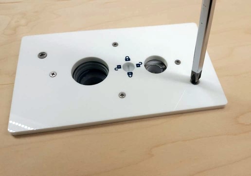
Checking The Unlock/Lock Screw
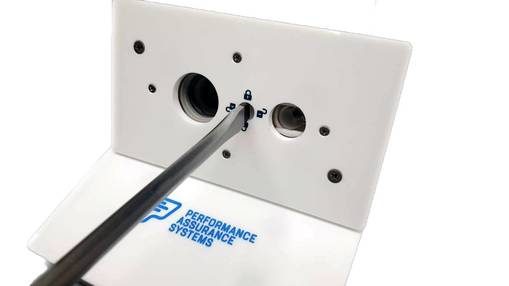
Note: Screwdriver must fill the CAM slot as completely as possible. Using a screwdriver that is too small may result in damage to the CAM.
Figure 1
Step 1
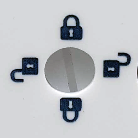
LOCK/UNLOCK SYMBOL
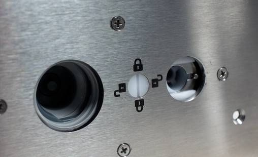
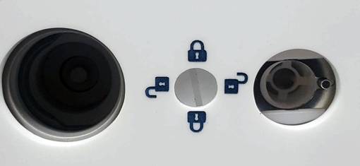
At the 3:00 and 9:00 position you see the UNLOCK symbols and at the 12:00 and 6:00 position you see a LOCK symbol. When you rotate the screw 360 degrees you should feel a slight resistance at the 3:00 and 9:00 positions, and at the 12:00 and 6:00 position it should feel free. The resistance at the 3:00 and 9:00 positions is the cam part of the LOCK/UNLOCK SCREW working to push the
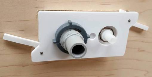
The LOCK/UNLOCK SCREW is designed to turn 360 degrees in either direction, so turn the LOCK/UNLOCK SCREW either direction a full 360 degrees. If the LOCK/UNLOCK screw rotates 360 degrees everything is normal. Now would be a good time to test fit the inserts. Lock the 3/4” and 3/8” challenge and test port inserts into place and release them 3-4 times each. They should snap into place firmly and release with a slight tug in the unlock position.
The inserts fit snugly and will loosen with use over time. If they fail to pop out immediately, ensure the CAM is in the unlock position and push against the face of the port with one hand and gently pull downward on the insert. It should disengage from the port with minimal effort. Then rotate the CAM to the unlock position for the opposite insert and repeat the process if necessary.
Figure 2
See Figure 3
Take a #2 square blade screw driver and place it in the LOCK/UNLOCK SCREW hole as shown previously in FIG2.
Figure 3
See Figure 4
Figure 4
Download Template
VIEW OUR .PDF TEMPLATE.
AVAILABLE FOR DOWNLOAD
To have the PASport device installed by our Performance Assurance Systems installation team, or to become a certified installer… please contact us today by calling
888-296-7775
STEP 1
INSTALLATION INSTRUCTONS
INSTALLING PASport
Versions 2.0 & 2.1
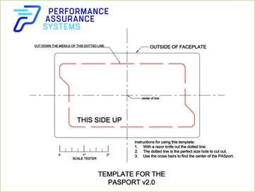
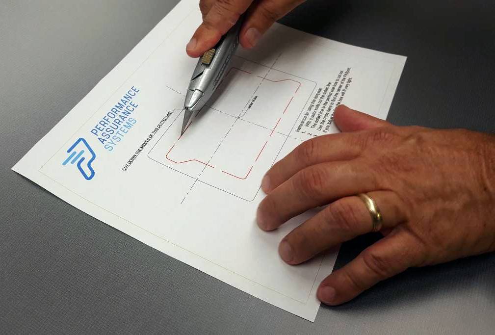
Find the template located in the box with your new PASport. Use this template to cut the hole to the correct size and shape, follow the instructions on the template directed. See Fig 5.
Figure 5
STEP 2
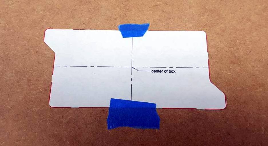
Place the template on to the material you are going to cut. The PASport is designed to be mounted into materials up to 3⁄4” thick. Make sure you have the template placed with CORRECT SIDE UP. See Fig 6. The unit will not fit through the hole if you cut it upside down!
Figure 6
STEP 3
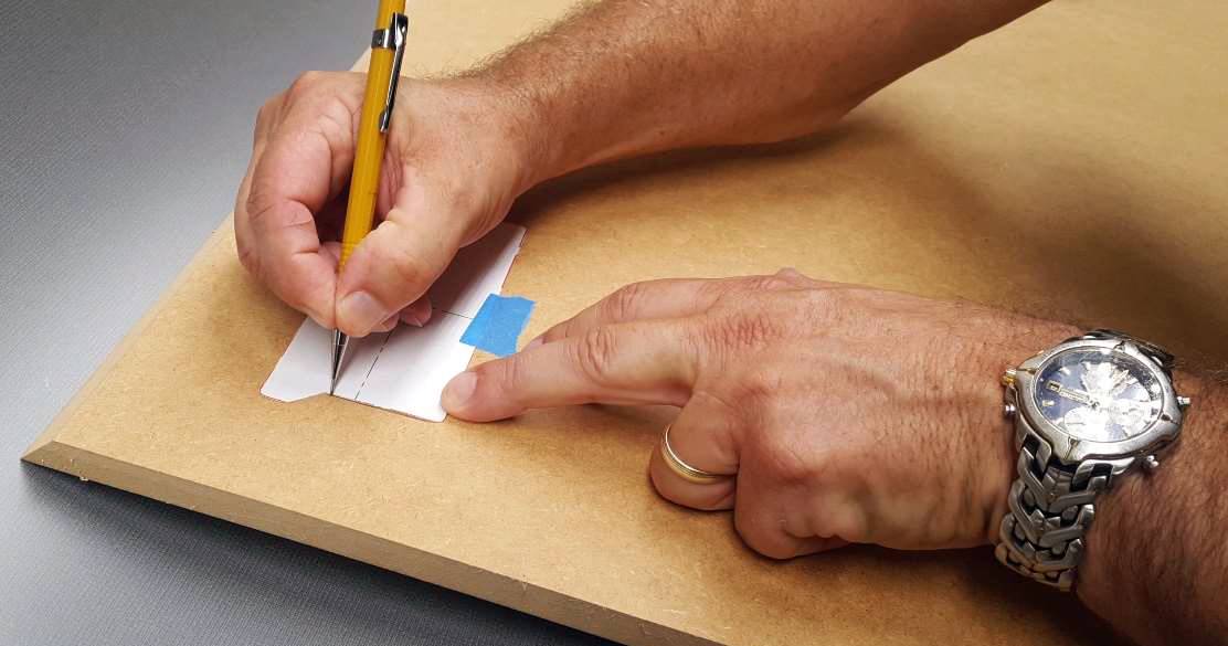
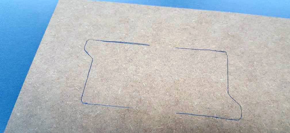
Draw a line around the outside of the template. Make sure you put the template right side up. When you have finished tracing it, it should look like Fig 7.
Figure 7
Cut the hole using the safest method possible using the correct tools for the material being cut. Be sure to follow all local, state, and national codes & safety requirements.
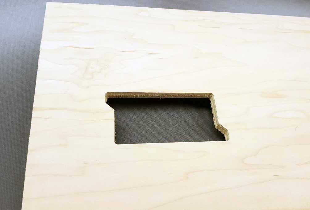
Make sure you cut the hole as accurately as possible, there is not much margin for error. The hole should look like this when you are done. See Fig 8
Figure 8
STEP 4
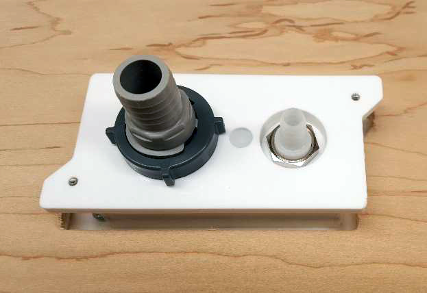
Insert the PASport through the hole. Once it’s through the hole you must secure it to the material with the built-in flip out ATTACHMENT CLIPS. See Fig 9
Figure 9
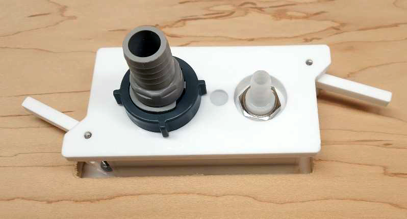
The ATTACHMENT CLIPS are connected to the PASport body with a screw that is mounted on the face of the unit. Turn the material you are attaching the PASport to over, so you are looking at the front. Securely holding the PASport centered in the hole, use a #2 Phillips head screw driver, tighten the attachment clips and secure the box by turning the screw clockwise. See Fig 10

